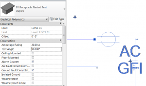
Often, when creating a family in Revit, such as an electrical switch or receptacle, there are a number of varieties that we want to be able to indicate on the actual drawing plan rather than scheduling them, as we would with most other families. This is most easily accomplished by creating an annotation tag that works with the family or by including a nested secondary annotation that changes for each type. Both methods have their advantages and disadvantages.
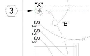
Using a nested symbol allows the designer to select the type of fixture and will automatically place the secondary symbol in a relative position to the primary symbol, chosen when the family is being created. The inherent limitation is that this additional, secondary symbol is locked relative to the primary symbol;if the family is rotated to be placed on a wall, the secondary annotation is rotated as well (see picture), and if that secondary annotation is interfering with other graphical elements, the entire family has to be moved. Additionally, if a device contains multiple accessories or falls under multiple categories, a new symbol must be created for each of these types and can become cumbersome.
Using a tag, on the other hand, can be handy because it allows the tag to be re-positioned relative to the primary device symbol. Importantly, this tag will also remain properly oriented to the sheet view.It’s possible to create a tag that works specifically with a family type that is more dynamic and will generate a list of identifiers based on each accessory chosen. The greatest challenge in this instance is the fact that each device being placed which requires a secondary symbol has to be tagged and have that tagged re-positioned, as the tag will be placed with the origin directly on top of the device. Additionally, if multiple tag types are required, it becomes more cumbersome as the designer has to choose from the types of tags to indicate which information is shown or else tag a device multiple times.
I set out to create a solution that gives the best of both methods. The positive characteristics I want:
- Auto-tagging in a desired location
- Fully movable secondary symbol capable of orienting to the sheet
- Dynamic secondary symbol that is able to show multiple accessories
- Secondary symbol able to automatically show additional information when required
To illustrate how all of these are able to be accomplished, I’ll step through the elements of the completed receptacle family:
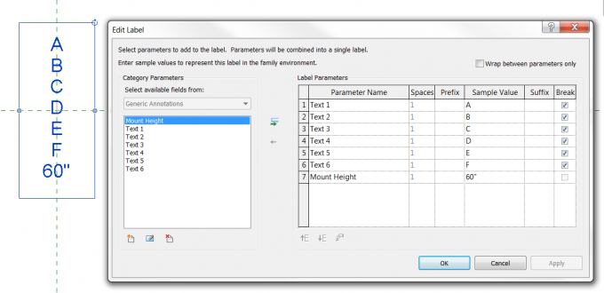
Creating the nested “tag” is very similar to creating a typical tag family. The parameters must be coordinated with the family to allow the two to communicate. If there are different types of tags – in this case I’ve created one that shows the device mounting height, and one that does not – then, duplicate the tag and add whatever additional information desired to the new tag and load it into the base family. These tags can be toggled in one of two ways, via a Boolean (yes/no) parameter, which itself can be toggled via a formula, or via the Family Type parameter type, which must be controlled by selecting the family type, a method which, in my opinion, is significantly more cumbersome to implement and to use. I’ll be using formulas to control the visibility of my tags, as seen below: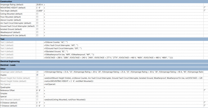
Now that the tag is created, nesting it into the base family in a manner that provides us fully movable and orientable functionality is the last and hardest step. This is accomplished by using “points” which are comprised of two reference lines locked to 90°. Three points are required to provide full X translation, Y translation, and rotation capabilities. The first point should be located as far from the base symbol as you anticipate the tag will need to be located; crossing the tag beyond this “origin” will cause one or both of the distance parameters we will be using, to change signs which will result in an error in Revit.
The next two points are set on top of each other. It will be easiest to work with one of these points oriented at other than 0° to prevent accidentally locking to a reference plane, or creating Automatic Sketch Dimensions that over constrain the family. Now dimension and create instance parameters for both the X and the Y separation between the origin point and the point that is oriented the same as the origin. The third point, which has a different orientation to the other two, should now have its orientation controlled by assigning an Angle parameter to it that controls it relative to the other non-origin point. Place, and rotate the tag (or multiple tags if providing varying, non-text information) to match the off-axis point. In each of the tags, I’ve included two invisible lines that mimic the reference points in the base family. Use these lines to lock to the point that is free to rotate and assign the same Angle parameter to these tags.
Now, examining the finished product, we’re able to see that we have the positive qualities we listed earlier. The one downside is that the angle for the secondary symbol must be manually input. Perhaps I’ll be able to create a solution through Python scripting within Revit, which I’ll be exploring in my next blog post.


