Introducing the Basics
This article is the first in a series discussing the lateral force resisting system (LFRS) for buildings. There is much to cover on this topic and thus the basics of a lateral system must be discussed first. To understand clearly how it works, we will discuss the following items:
- Define what an LFRS is and the different types
- Answer a few basic but important questions
- Learn what materials can be used and their corresponding building codes
- Illustrate the application of an LFRS
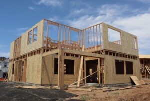
A lateral force resisting system (LFRS), or lateral system for short, can be defined as a specifically designed structure as part of a building that resists against lateral loads such as wind or seismic. There are three main types used in a building – braced frames, moment frames, and shear walls. Below are examples of each. The three types will be discussed in further detail in later articles.
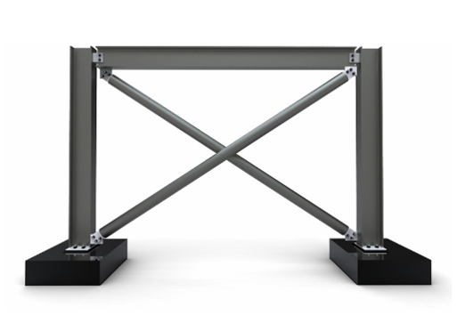
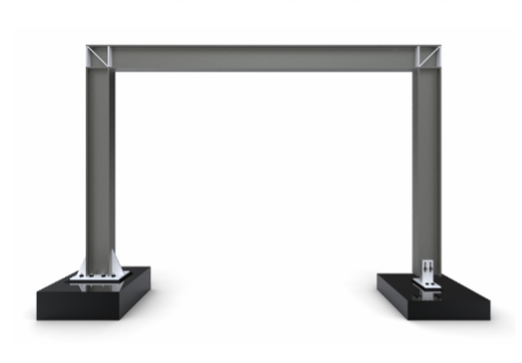
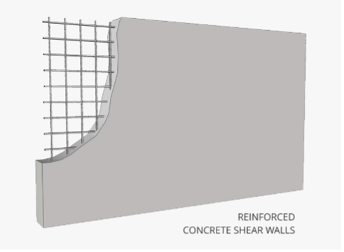
These illustrations depict the basic structure of each type of lateral system. For multi-story buildings, each frame or wall is built and connected at the top and bottom to resist the lateral loads from top to bottom of the building.
Why is a Lateral Force Resisting System (LFRS) Important?
The two main lateral loads an LFRS is designed to resist are wind and seismic. An LFRS is essential not only to the stability and longevity of the structure to resist these loads but also to the lives of its inhabitants. Without an LFRS designed specifically for each building it could suffer extensive damage, and worse, could cost lives. In short, a lateral system is critical to any structure/building.
How Does an LFRS Work?
The three main types of lateral systems, illustrated above, all work in basically the same way, in that, they all “brace” the building and transfer the lateral load to the foundation and then is dissipated into the earth.
Where is an LFRS Located in the Building?
There is much consideration as to where the lateral system is placed within the building, but it is usually preferred to be located on the perimeter of the building and can either be exposed or concealed within the walls depending on the architect’s preference. Lots of communication between the architect and structural engineer is had in the early stages of design to figure out the best location for the lateral system.
Types of CMU
Steel, concrete, wood, and concrete masonry units (CMU) are the four main building materials, of which two or more are often used in the construction of a building. The pre-requisite to designing a building with any of these materials is to know their governing codes they must comply with, in which, each building material has its own code, below:
- Steel – Specification for Steel Buildings, by American Institute of Steel Construction (AISC 360)
- Concrete – American Concrete Institute (ACI 318)
- Wood – National Design Specification (NDS) for Wood Construction, by American Wood Council
- Concrete Masonry Units (CMU) – Building Code Requirements and Specification for Masonry Structures, by The Masonry Society (TMS 402/602)
These codes are the minimum standard to which the structure must conform. Below are a few basic illustrations of how wind and seismic loads affect buildings and the lateral systems resisting the loads.
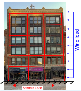
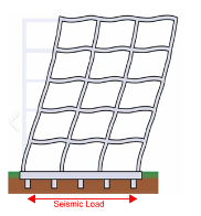
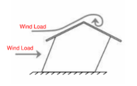
As illustrated above, the lateral system is integrated into the building and braces the building against wind and seismic loads. The example of an overlaid frame is a real building with a multi-story lateral frame overlaid to show a basic illustration of the lateral support structure that is built behind the brick façade.
This concludes some of the basic items of a lateral force resisting system. Further in-depth discussion will be continued in subsequent articles.