A reoccurring problem I see when it comes to utility design for multi-family projects is not fully thinking out the beginning 2D geometry design of the water, sanitary, and storm sewer lines. It’s very easy for new engineers to focus only on specific design criteria and miss the overall picture of how all the utilities will fit into the project site. I have made this mistake many times and it may be helpful for me to share my lessons learned.
Skipping Research
Do your research! Always know what jurisdiction, area, or city the project site is located in and what county or municipality will be reviewing the submitted plans. There are many a lot of factors stemming from this that can affect how you need to design your utilities, such as as how to submit the civil plans, what the design criteria checklist is for that area, and creating points of contact within the city to clarify any design questions just to start. That could all be it’s own blog post! Suffice to say, doing your research is time intensive but crucial for accurately creating your utility design.
Skipping 2D Drawings
Once you know your basic design criteria for the water, sanitary, and storm lines, you should draw out the utilities in 2D, either in CAD or by hand. Never jump right into drawing in 3D pipe networks. I have wasted a lot of time on utility design doing this, just to be forced to redraw due to design conflicts such as the city not allowing my original design.
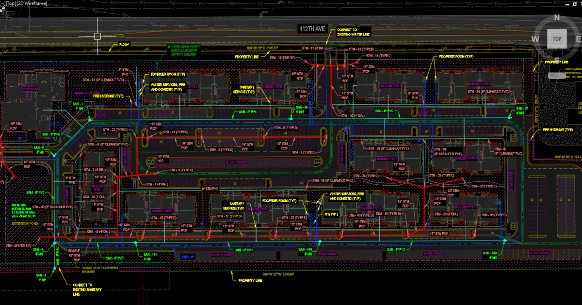
The basic design aspects of drawing in the water, sanitary, and storm sewer lines are:
- Easement width required for each utility
- Minimum depth of each utility
- Pipe material allowed
- Minimum spacing required in between each utility.
A lot of multi-family projects love to maximize full utilization of their space by cramming in buildings, amenity spaces, clubhouses, and more, which leads to reduction of the width of the roadway. That in turn makes it very difficult to place all three utilities within the roadway. General rule of thumb: if your roadway is 24-26’ wide, fitting in water, sanitary, and storm sewer lines can be very difficult (but usually not impossible) depending on the geometry of your site.
Forgetting to Ask For Review
Once you have all utilities drawn in 2D, it’s always good to reach out to your point of contact of who will be reviewing your plans. Send them a basic general utility layout design and ask them if they could do a quick review to see if they have any initial concerns. This will save you tons of time in the long run, TRUST ME! Unfortunately, sometimes the point of contact doesn’t have the time or is not very receptive of you asking for a quick review. Even so, sending it in is always worth it for when that person can review.
Avoided All Those? Now It’s Time for 3D!
With luck, the city contact will reply back with some comments for you to take into consideration in the 2D design step. Once you address those, then you are good to go to start drawing in your utility 3D pipe networks in CAD. After that, you can cut profiles, check utility elevation conflicts, set up your sheets, finish your proposed surface, run hydraulic calculations, finish that report, maybe do a utility report, and so on.
So much to do and so little time! Oh, the joys of civil engineering. Sometimes it seems like it’s the design no one cares about, but it’s one of the main pillars in any multi-family project, and vital to a successful project.