1-Line Diagram – What is it and why do I need one?
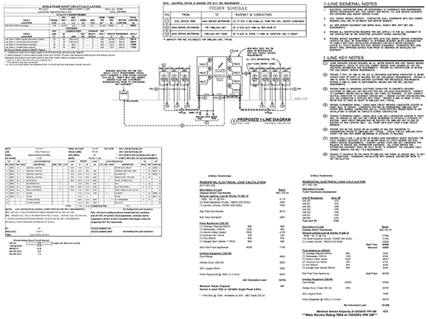
You may have been advised by the Authority Having Jurisdiction (AHJ) when you attempted to submit your drawings for plan review that your planned project requires that a “1-line Diagram, load and short-circuit calculations” be provided as part of the planned submittal for review and approval. You may have never heard the term “1-line diagram” before. For those not so electrically inclined, this “1-line diagram” may be a strange term, but for others in the trade, it is actually a very common term. A very basic definition of a 1-line diagram is that it is a schematic diagram representing the proposed new or modified electrical service and distribution equipment and all associated wiring and grounding details for the project. On single-family homes and duplexes, they are not typically required unless the calculated dwelling unit load and service rating is over 200 Amperes.
Depending on the type and scope of a project, the AHJ may require that a 1-line diagram and all associated calculations, panel schedules, and wiring and grounding details be provided to ensure that the project has been properly designed. They are typically required for almost every commercial project including multi-family type buildings (apartments, townhomes, and condominiums). Where multi-meter assemblies are used, a 1-line diagram is typically required by the AHJ.

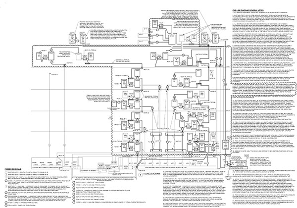
1-lines can vary from very simple to very complex depending upon the project scope and function. For example, a single-family home would be about as simple as you can get, but if a generator is needed, it is a bit more complicated. A Hospital, on the other hand, is very complex by comparison as it includes an Essential Electrical System (Standby power for Life Safety, Critical Care, and Equipment) as well as the normal power distribution system with special considerations for a Health Care Facility. A Data Center can also be a whole other level of complexity as there is a major redundancy component that doubles the amount of equipment (at a minimum) to provide the necessary reliability that a Data Center requires.

The size and capacity of an electrical service and distribution system are determined by performing electrical load calculations per NEC Article 220 to establish the minimum service capacity and rating for every point in the system. Short circuit calculations are performed to determine the short circuit current interrupting rating (SCCR) required to properly protect the service and distribution equipment in the event a fault (or short circuit) occurs. The resultant energy from a short circuit can result in a catastrophic and potentially deadly explosion if electrical service and distribution equipment is not properly rated to interrupt the available fault current. Short circuit analysis and proper equipment selection based on the results of the analysis ensure a safe electrical installation.
The main issues AHJ’s are concerned with are calculated loads and short circuit currents available with correct wire and equipment sizes/ratings. This information is indicated on the 1-line diagram to allow the AHJ to confirm the adequacy of the proposed equipment configuration and ratings. Your local AHJ has the authority to require all of this information under NEC 215.5 (Diagrams of Feeders) in addition to any local legally adopted amendments or statutes.
In conclusion, if you are tasked with having to provide a 1-line Diagram (and all associated information) by your AHJ for your project, do not worry as EVstudio is ready, willing, and able to provide you with all the drawings and necessary information for a proper submittal. Contact us today!


