This article is intended for a person having basic knowledge and familiarity of AutoCAD who needs a method for accurately locating an element in a drawing relative to other elements. There are other methods to accomplish the task of accurately locating objects relative to other objects, but this is what I do.
When working in AutoCAD it is inevitable that line work, a block reference, an object, a block, or group of objects needs to be rotated to an odd or unknown angle in the drawing.
This example is for an architectural site plan with irregular lot line distances and angles. Here are the steps involved for this architectural site plan example.
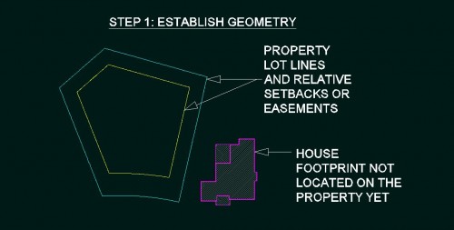
Step one: Establish geometry of property lot lines and house or building footprint geometry, which is probably easier done independently just to get them in the drawing.
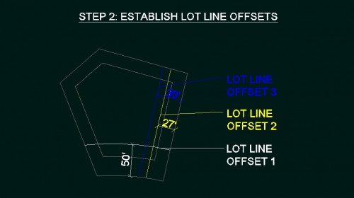
Step two: Establish lot line offsets with the three pre-known distances to set up rotation origin point and what will soon to be a reference point for the rotation command.
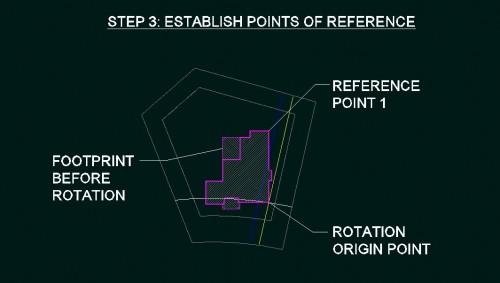
Step three: Next locate the structure to the two intersecting lot line offsets. This point becomes the rotation origin point. Then establish another point on the structure that is to be the first reference point for the rotation command. In the graphic this is labeled as reference point one.
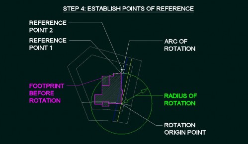
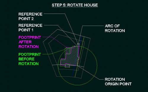
Step four: Draw a circle with the center at the origin point of rotation and at the radius of reference point one. The circle should intersect the lot line offset that is to be the second and final point at which we align and affix the building to the property, reference point two. I have also labeled the arc, or portion of the circle, that is to indicate the distance that the rotation will have, which will always vary depending on the how the property and structure relate to each other.
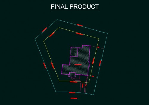
Step five: Now we are ready to use the rotate command to align the structure to the correct position on its property. After engaging the rotate command, selecting the rotation origin point, entering “r” to make the rotate command require a reference point, then click reference point one and rotate the structure by then clicking reference point two. The object snaps used are endpoint or center for the rotation origin point, endpoint or intersection for the first reference point, then intersection for the final point where the circle intersects with the lot line offset line. Then just delete the lot line offsets and circle that are no longer needed and add any other necessary site information like driveway, walkways or landscaping, text etc. There, we now have the structure accurately located relative to the property boundaries.
For other professions and disciplines that use AutoCAD, the method is basically reduced to rotation of an object with use of an origin point, a radius of rotation which is common to both what is being rotated and the final point of the rotated objects. The use of specific object snaps are at the discretion of the user. Hope this is helpful!