While BIM has been widely adopted by the Architectural community, it truly is the rare project that has every discipline on board in a fully integrated BIM process. The Centers of Standardization (COS) projects currently being designed and constructed by the Army Corps of Engineers require this process which offers a unique opportunity to focus on the processes and benefits of executing BIM to its full potential.
Having been a part of numerous United States Army Corps of Engineers (USACE) projects in my work with Bentley Systems I understood they can be intimidating in terms of the formalized process. But the CAD manager in me can appreciate where the Army Corps is headed and the need to lay down some ground rules.
One of the first steps required is to actually plan out your team’s BIM process and document it. This process is called for in the project RFP (Attachment F) and then further detailed in a link you can find in the RFP or in the Army Corps CAD-BIM Technology Center.
The latest edition of the Army Corps BIM Execution plan developed in concert with the Computer Integrated Construction Research Project at Penn State (CIC) is a great tool for getting everyone on the team talking about what it really takes to develop a fully integrated BIM project. I highly recommend this as a starting point for anyone doing a large BIM project whether it be USACE or otherwise.
The Execution guide goes into great detail, but as a summary you could say it basically outlines Who is going to What When and Who they are going to pass that What to When they are done. These are important questions because BIM at its best is about Collaboration fueled by Re-using as much data as possible.
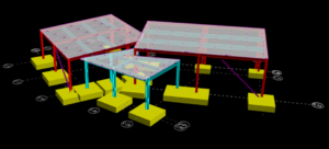
For example, in our USACE COS Ft. Hood project our Structural engineer is designing our concrete and steel frame using Bentley RAM Structural systems which allows him to design, analyze and detail the entire structural system. He can then pass this model to his colleague who then documents the whole process in Bentley Structural Modeler which also connects is modeling process to the rest of the team modeling the projects Architectural, Mechanical, Electrical, Fire Protection and more.
When compared to a more traditional process of drafting out a 2d structural grid and drafting and sizing each beam individually which the Architect then has to manually check for potential conflicts with other disciplines then benefits of re-using data are no longer theoretical. These benefits add time savings to the project and create real value for the client by streamlining manual processes that always contain the potential for error.
However, as much as I love technology, the vehicle is only as good as the driver. Not every project requires the formalized documentation of an Army Corps project, but any project can benefit from the processes and skills that EV Studio has developed by working on USACE projects.