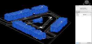
Simply put, when you go into the Parts and Families in Bentley Architecture’s Dataset Explorer, you will find a way to identify a pattern using the extraction method but this pattern is only going to change the way a cut view (section, plan cut, etc) displays. I think there is probably a better method with Dynamic Views, but for now let’s focus on Extractions, because many USACE work flows still require Extractions.
So to apply a pattern to a wall in a forward (Elevation) or…reflected view (RCP). You have to define a “dummy part” with the pattern you want and then assign that dummy part to the real part using a simple xml file edit.
Now if that sounds a bit complicated….listen to this verbage attached to the sample xml file you have to edit.
“Since there is no field in the Part schema today to allow a user to identify a hatch pattern for Forward and
Reflected views. This capability is accomplished with the part mapping file. This contains a series of records. Each record has a Section Part Element the contains a ForwardPart Element and a ReflectedPart Element. Each of the elements has an attribute family=”…” and part=”…”. These attributes are Family and Part names that exist in the current dataset. Entities that are extracted into the Forward view and have a part assigned to them that matches the SectionPart are created using the properties of the FowardPart entry. This includes symbology and hatching attributes. The same is true for elements in the Reflected view. Fill attributes do not apply to the foward or reflected view. ”
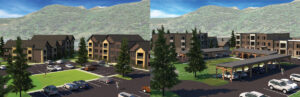
This is the forward elevation Extraction.
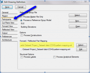
I copied the sample XML file that you can see when you first click on and placed it in the project directory, and edited it.
Text from XML
<?xml version=”1.0″ encoding=”Windows-1252″?>
<!– This is a sample Part Mapping file. This file was introduced with the addition
of the Forward and Reflective View hatching capability. Since there is no field in
the Part schema today to allow a user to identify a hatch pattern for Forward and
Reflected views. This capability is accomplished with the part mapping file. This
contains a series of records. Each record has a Section Part Element the contains
a ForwardPart Element and a ReflectedPart Element. Each of the elements has an
attribute family=”…” and part=”…”. These attributes are Family and Part names that
exist in the current dataset. Entities that are extracted into the Forward view and
have a part assigned to them that matches the SectionPart are created using the
properties of the FowardPart entry. This includes symbology and hatching attributes.
The same is true for elements in the Reflected view. Fill attributes do not apply
to the foward or reflected view. –>
<TriForma>
<SectionParts>
<Version major=”1″ minor=”1″/>
<SectionPart family=”C1010″ part=”CMU:04____1HR”>
<ForwardPart family=”C1010″ part=”z_cmu unifier” />
<ReflectedPart family=”C1010″ part=”z_drywall unifier” />
</SectionPart>
<SectionPart family=”C1010″ part=”CMU:06____1HR”>
<ForwardPart family=”C1010″ part=”z_cmu unifier” />
<ReflectedPart family=”C1010″ part=”z_drywall unifier” />
</SectionPart>
<SectionPart family=”C1010″ part=”CMU:08____1HR”>
<ForwardPart family=”C1010″ part=”z_cmu unifier” />
<ReflectedPart family=”C1010″ part=”z_drywall unifier” />
</SectionPart>
<SectionPart family=”C1010″ part=”CMU:10____1HR”>
<ForwardPart family=”C1010″ part=”z_cmu unifier” />
<ReflectedPart family=”C1010″ part=”z_cmu unifier” />
</SectionPart>
<SectionPart family=”Wall Leafs” part=”Brick”>
<ForwardPart family=”Wall Leafs” part=”Brick_Pattern_Elevation” />
<ReflectedPart family=”Wall Leafs” part=”Brick_Pattern_Elevation” />
</SectionPart>
<SectionPart family=”Wall Leafs” part=”CMU”>
<ForwardPart family=”Wall Leafs” part=”CMU_Pattern-FW” />
<ReflectedPart family=”Wall Leafs” part=”CMU_Pattern-FW” />
</SectionPart>
</SectionParts>
</TriForma>
I then created the CMU and Brick pattern “dummy parts” directly from the CMU and Brick Wall leaf parts, but changed their pattern to be what I wanted to appear in the elevation and named them appropriately so they wouldn’t be confused with their wall leaf counter parts.
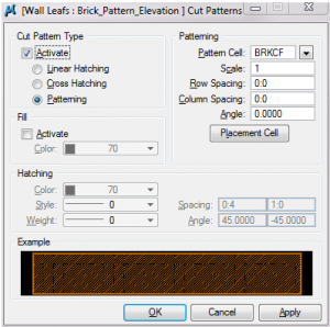
A word of caution, patterning seems to work better for some things than others. It is a great tool for simple patterns and for schematic design…but it doesn’t give you the same flexibility that you have with patterning the wall manually.
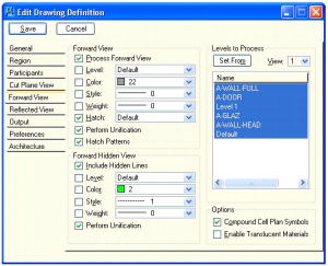
Oh, and don’t forget to turn on hatching in your extraction!
I will also be experimenting with using part mapping for other features like unification. Because there are some views where unification is good, and others where it is not, and turning them off and on for every extraction is both time consuming and prone to error.