As all architects and engineers using Revit know, the out of box settings are rarely what you need to produce a set of drawings for review. Namely, visual representation of modeled elements often does not match up with your intent. In order to bypass this, one must adjust detail level, enlist the use of the “Filters”, and edit the View Range that Revit has.
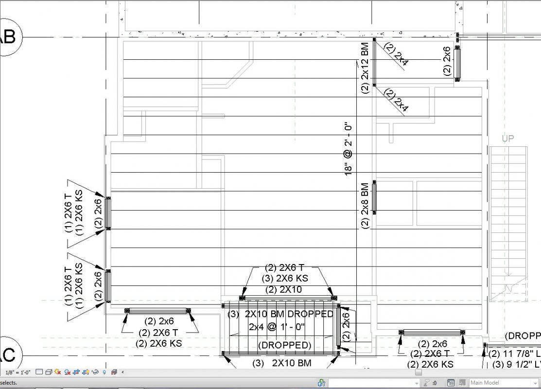
Above is a photo of a structural framing plan that is drawn using the native Revit settings. Joists show up as stick lines, bearing walls aren’t hatched, and the joists appear to run into the walls, rather than resting of top of them.
The first step in this process is to change the detail level from COARSE to MEDIUM. As you can see below, some walls are now hatched, the joists show the correct width, and provided that you have drawn the Structural Beam System to the outside of the studs in the walls, the joists will project over the walls.

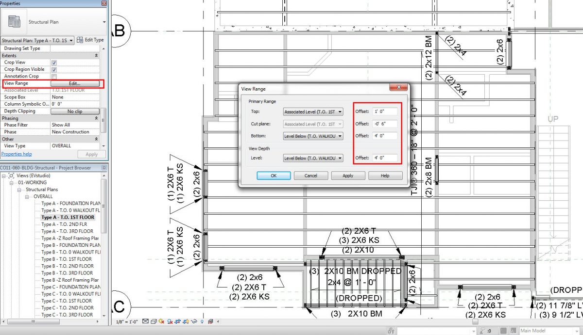
If the joists are still running into the walls and not appearing to project over the top, check the View Range. As you can see below, the View Range for this particular framing plan has been set to a structural framing view. The Cut Plane is 6” below the Finish Floor level and looking down. This will force Revit to cut through the joists and display the way you wish, with joists resting on top of the studs.
Finally, creating Filters will allow bearing walls and non-bearing walls to appear with the correct graphics. The Filters tab can be found under the Visibility/Graphics window.
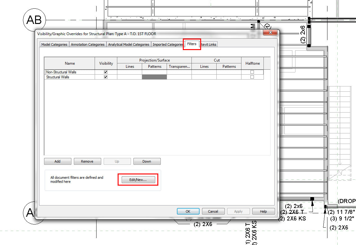
Go into Edit/New, then in the lower left, create a new filter called Structural Walls. In the Categories list, Check Walls. Under Filter Rules – Select Filter By: STRUCTURAL USAGE equals BEARING then click apply. Repeat the same steps for Non-Bearing walls with the appropriate selections. After clicking Apply again, you will be taken back to the filters screen.
*A side note: Coordination must occur between the architect and engineer in order to determine which walls are bearing. The bearing walls that are modeled in the project must have the Structural box checked in each wall’s properties for the above to work.

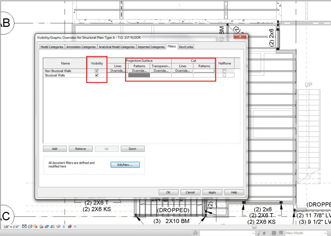
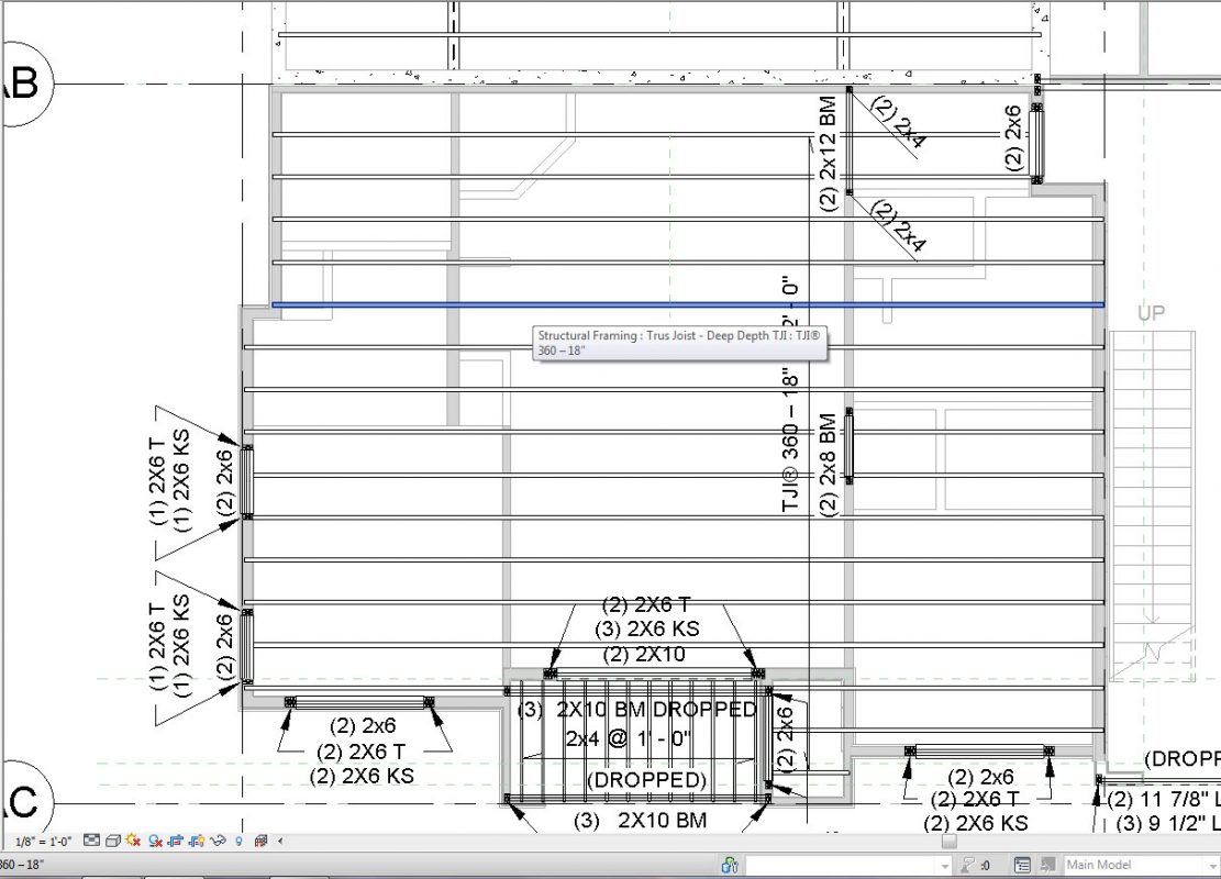
As you can see below, we want both Non-Structural Walls and Structural walls to have the Visibility box checked. Edit the Projection/Surface and Cut Patterns of each to Display Solid Gray for Bearing Walls and White for Non-Bearing Walls. Click Apply at the bottom and close the box and presto!
Your structural framing plan should appear like the one below.
In closing, Revit’s graphic display options can be greatly modified to suit an office’s or client’s wishes when it comes to how they are accustomed to seeing plans drawn. This is accomplished through the use of View Range, different Detail Levels, and Filters outlined above.